One thing with this amp is that there is no bias pot and the bias voltage is set to -46. This seems to have possibly caused a problem when the capacitors started to dry out. When electrolytics dry out they begin to have resistive quanlities as well as a capacitance. A less negative bias results in a greater current flowing through the tubes. Which could burn them out prematurely, or overload the plate and cause it to glow bright red (seriously shortening the tubes lifespan if not ending it right there).
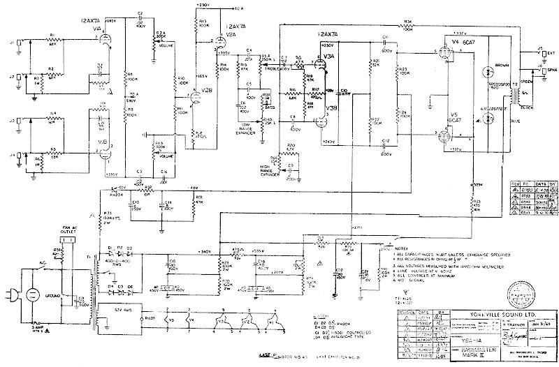
This is the schematic for my amp. Mine is either a later or earlier revision and has a few less parts plus runs a higher voltage to the preamp tubes.
Basically the main B++ power supply caps were replaced as well as a few others. A bias pot was added as well for a bit more versatility.
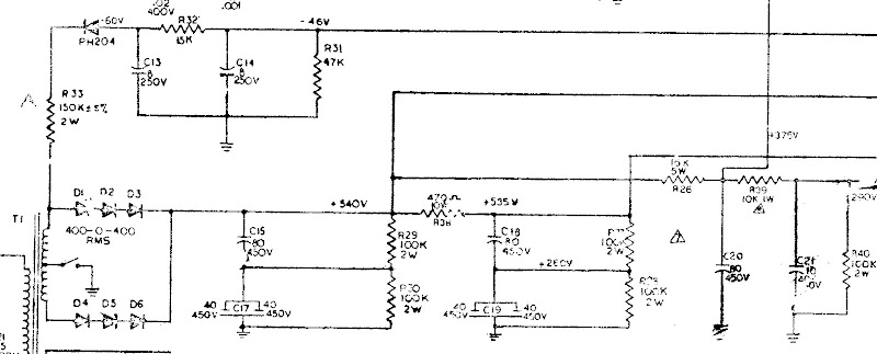
Heres a close up of the power supply section. C15, C17, C18, C19 and C20 were all swapped out for 100uF 450V nichicon electrolytics.
But one thing at a time. Going back to the bias problem. When I measured the bias had sagged to -41v.


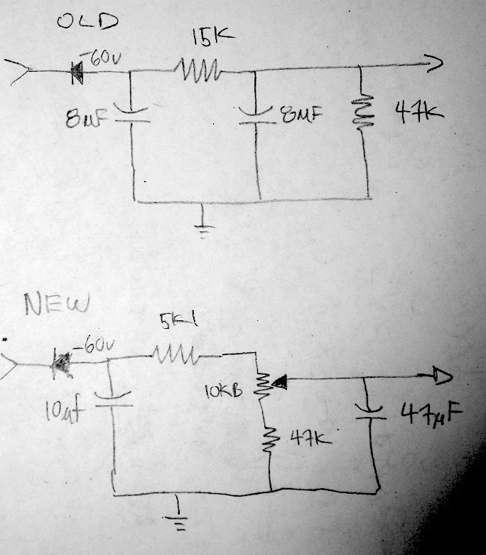
Looking back at the schematic, if C14 had even a somewhat large resistance, it would be in parallel with R31, effectively lowering its resistance and lowering the voltage drop across it. since the -46v comes from the voltage divider setup by R32 and R31, C14 developing a resistance would cause the bias voltage to become less negative. So i replaced both C14 and C15. C14 with a 10uf and then changed the circuit a bit to have a bias pot that can vary from about -44v to - 55v. Essentially R32 is replaced by a 5k resistor in series with a 10k pot. The wiper of the pot is connected to a 47uf cap and is considered the output voltage. The 3rd leg of the pot goes to R31 which remains unchanged.
Here is a sketch of the old and new bias sections
Here is some math showing the effect of the resistive qualities of a bad cap on the bias voltage

Heres the bias section modified with the pot. Also you can see the replacements for C15 and C19.

Heres C20, C16, C17 replaced. The holes are where the can caps used to be.

I also replaced a few resistors that were floating out of spec. And I changed R16 from 10k to 11k. The reason is because on my version the voltage at c20 is exactly 450 volts (if everything is ok) which is the caps rated limit. Although this is not likely a problem I bumped R16 up to 11k to reduce that voltage just slightly to around 442 volts.

And finally I also replaced C21 with a 10uf 450V xicon electrolytic. While doing this I melted a bit of one of the filter caps being careless with the iron. So I replaced it with a metal film cap of the same value (to the left of the yellow capacitor in the picture below).

No comments:
Post a Comment